Traffic Pursuit Unit arc42 section 5
Building Block View
5.1 White Box of TPU
The following figure shows the internal top-level decomposition of the Traffic Pursuit Unit. The decomposition is mainly driven by the deployment of these top-level building blocks to different hardware (cf. chapter 7). Note that the blue boxes are pure software blocks, while the white one is still a mixture of hardware and software functionality.
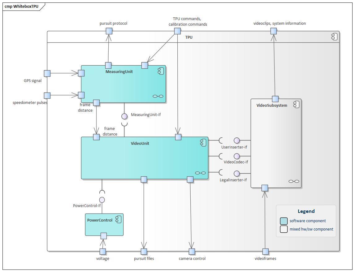
1. MeasuringUnit
is responsible for all measurements (speed, time, GPS data, temperature, pursuit data) and for the calculation and storing of all legally relevant data. It can run standalone, without being attached to the VideoUnit, doing simple pursuits without video. In this case it implements an own simple user interface by means of a keyboard with alphanumeric display.
2. VideoUnit
controls the operation of the MeasuringUnit (when it is not operating standalone). It collects all current data from the MeasuringUnit, formats it and dispatches it to the UserInserter and the LegalInserter for display.
It also implements the graphical user interface and the functionality for creating, storing and managing videos.
By communicating with the PowerControl module it performs a safe shutdown when ignition is being turned off.
3. VideoSubsystem
summarizes all hardware and software functionality running on the video boards. It handles all video operations from incoming video frames to their display on the screen including all transitions between analog and digital video signals. It contains the codec that compresses the video stream from recording and decodes recorded videoclips for playback.
4. PowerControl
is responsible for monitoring of the ignition state, in order to support a regular shutdown of the Linux system. After the shutdown the TPU can safely be powered off to prevent it from draining the battery of the car. When the ignition is being turned off, this component communicates this fact to the VideoUnit in order to request shutdown, and waits for the information that the system is safely shut down. Then it powers off the TPU.
Important Interfaces
MeasuringUnit-If
This interface provides all functionality to control and access the measuring functionality of the MeasuringUnit. It is implemented by remote procedure call, and can be accessed as well internally as externally by another node.
This functionality encompasses:
- operational control: setting the desired operation state of the MeasuringUnit (Idle, Calibrating, Measuring)
- status query
- reception of measuring data on a periodic base
- current time as received by GPS
- voltage and temperature of the unit
- current speed
- pursuit measurements in case of performing a pursuit
- calibration status in case of performing a calibration
- performing and managing pursuits
- retrieving or printout of calibration and pursuit records
5.2 White Boxes Level 2
1. MeasuringUnit
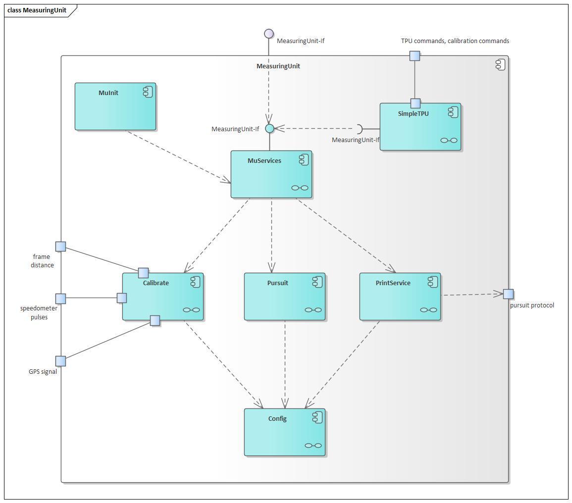
The following figure shows the internal structure of the MeasuringUnit.
1.1 MuServices
contains the services offered by the MeasuringUnit and offers these via an RPC interface. These services are:
- deliver periodic updates of environmental and measuring data
- perform a pursuit
- perform an automatic calibration
- perform a manual calibration
- print pursuit protocol
- print calibration data
1.2 Pursuit
implements the operational logic, all calculations and storage of the data of a pursuit.
1.3 Calibrate
implements all functions to perform an automatic calibration and to permanently check the validity of the current calibration data.
1.4 PrintService
handles layouting and formatting of documents describing pursuits or calibrations and renders these according to the type of the connected printers. Implements a print queue to print the documents out to the attached printer.
1.5 SimpleTPU
implements the user interface and control logic to run a TPU without video functionality based only on the hardware and software of the MeasuringUnit.
1.6 Config
contains all configuration data concerning the behaviour and the legal parameters for the measurements.
1.7 MuInit
runs only once to initialize and start up all services within the MeasuringUnit.
2. VideoUnit
The following figure shows the internal structure of the VideoUnit.
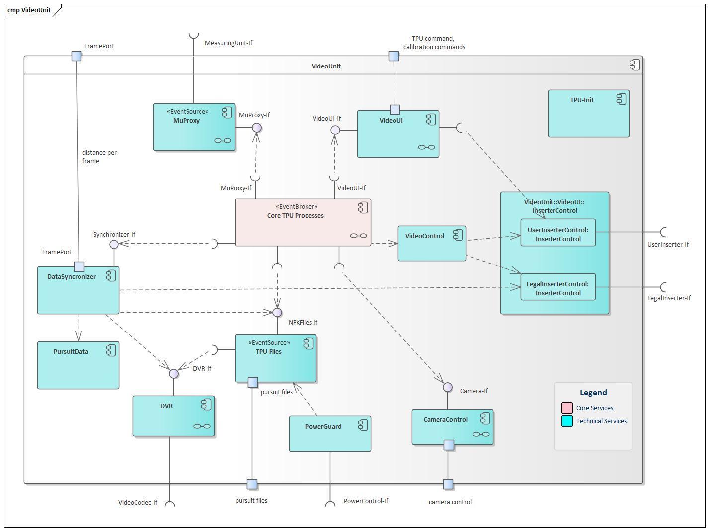
The VideoUnit supports the Core TPU Processes (shown in pink in the above picture) with a set of autonomous technical services which control and monitor the various hardware units, i.e. the MeasuringUnit, the cameras, the VideoInserters, the DVR and the PowerControl.
All these services are implemented as concurrent processes initialized by TPU-Init.
2.1 Core TPU Processes
implements the processes of the Traffic Pursuit Unit as shown as use cases in chapter 1.1, from configuration through measuring to presenting the results of the pursuit.
2.2 TPU-Init
starts up all modules running within the VideoUnit. It opens the communication channels to the MeasuringUnit, the VideoSubsystem, the cameras and the PowerControl, establishes the communication to the devices and brings the whole system into a defined start state.
2.3 MuProxy
handles all communication to the MeasuringUnit. It provides commands to completely control the MeasuringUnit. It receives regular updates of all data acquired by the MeasuringUnit and caches them, so that the newest values can quickly be retrieved. Whenever an update arrives it sends an event to the VideoUI, so that the current application will be notified (see 8.2).
2.4 VideoUI
offers a user interface toolkit based on forms that are displayed on the UserInserter. It offers a predefined set of forms that are made up of arrangements of data fields and buttons, and a set of selection functions and editing functions for these fields. The toolkit implements the concept of a stacked UI (see 8.2).
2.5 DataSynchronizer
receives Distance Per Frame records at a speed of 25 units per second from the MeasuringUnit. It combines this data with the Pursuit Step (once per second) and formats the output for the LegalInserter. It feeds this data to the LegalInserter by taking care that the inserter is neither overrun nor underrun.
When a video is started or finished, this component coordinates the operations of the components NFKFiles, LegalInserter, PursuitData and DVR.
2.6 PursuitData
stores the Pursuit Step per second combined with the current RecordingTimestamp to the Pursuit Step File. It also offers functions for reading such a file step by step, in order to replay the stored information on the UserInserter aligned to the video recording. This file will become part of the Pursuit File, created by TPU-Files.
2.7 TPU-Files
manages all Pursuit Files created by the TPU and takes care of the available disk space. It creates the files for recording and checks that they do not exceed configured limits or leave insufficient free disk space. When a USB stick is inserted, it copies as much as possible of the not yet copied Pursuit Files to the stick. Just before copying, it creates the Pursuit File by combining the video, the Pursuit Step File and the printout. When disk space runs low, it deletes those files that already have been copied to a USB stick.
2.8 DVR
The DVR component is responsible for video recording and playback. When not recording, it holds a configurable ring buffer of the current video in memory, that can be prepended to a video on recording start. On recording it keeps a counter of the current frame that can subsequently be used to identify and directly access any frame on playback.
2.9 VideoControl
starts and initializes the two InserterControls (i.e. the UserInserterControl and the LegalInserterControl) and offers functions to control their operation, including camera selection or muting video input.
2.10 InserterControl
Exists as two instances, as explained in VideoControl. It implements the communication protocol to the two video inserters (i.e. the UserInserterControl and the LegalInserterControl). It offers functions to compose telegrams, and formats and transmits them to the corresponding inserter. It receives and parses acknowledge telegrams from the VideoSubsystem and throttles transmission in order to limit the count of unacknowledged telegrams and prevent the inserter from being overrun.
2.11 CameraControl
offers all functions to control a zoom camera. It continuously communicates to the camera to acquire its operation status, and can tell when a zoom operation has successfully been completed.
2.12 PowerGuard
receives the power off signal from PowerControl and waits for TPU-Files to signal a safe shutdown.
3. VideoSubsystem
The following figure shows the internal structure of the VideoSubsystem. Note that the green building blocks are pure hardware functionality whereas the blue ones are software modules.
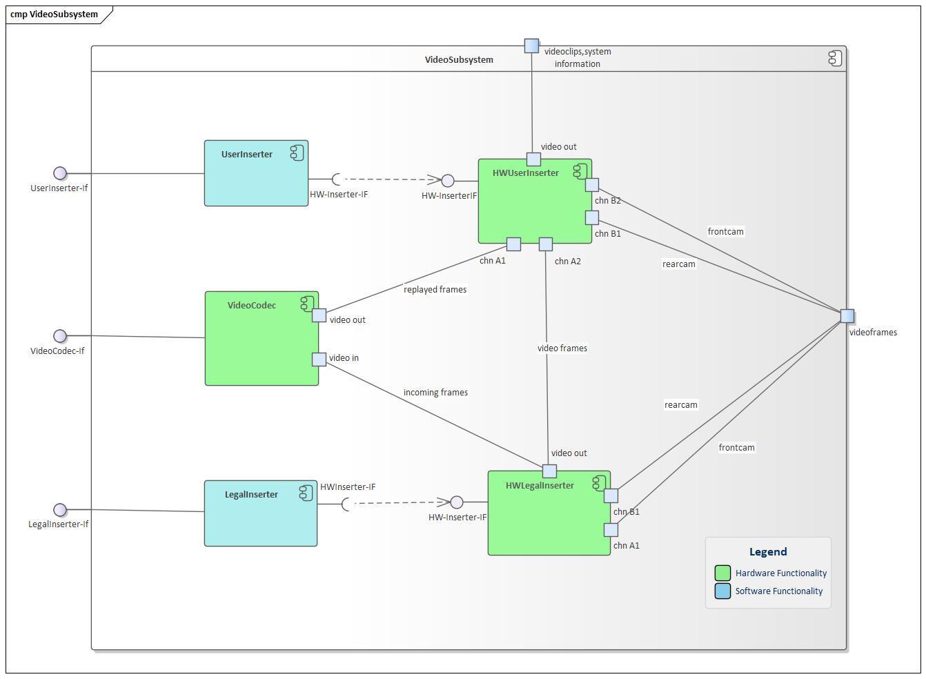
3.1 HWUserInserter
models the hardware functionality of the UserInserter node. It receives video frames from various sources and augments them by inserting text according to the controls from the UserInserter.
3.2 UserInserter
augments the video stream by inserting text and renders it for the display. This text is only shown to the police officer and is not stored in the videofile. Depending on the current operating mode, this component displays graphical elements for the management user interface or it shows current state information. The latter contains all relevant current information for the police officer. This information is displayed in a big font for good readability. This data contains: date and time, current speed, available satellites, free storage info for the harddisk and the USB stick, information of active copy operations to the USB stick. During a pursuit, additionally the time and the length of the pursuit and the current maximum violation is displayed.
3.3 HWLegalInserter
models the hardware functionality of the LegalInserter node. It receives video frames from various sources and augments them by inserting text according to the controls from the LegalInserter.
3.4 LegalInserter
Similar to the UserInserter this component also augments the video stream with text, but this information is stored in the video file and not only displayed on the screen. Contrary to the UserInserter the text is in a small font at the bottom of the display, to avoid obscuring any relevant parts of the videos. This text line contains all data necessary for legal evidence: a frame counter, date and time, current speed, the amount of time elapsed since the start of the pursuit, the current length of the pursuit, the distance covered during one frame, the zoom factor of the video camera and the GPS coordinates.
3.5 VideoCodec
models the functionality of the HW codec. It transforms the incoming video frames into a digital stream that is captured by the VideoUnit on the PC board. In the opposite direction it accepts digital streams and transforms them into a video stream to be displayed.
5.3 White Boxes Level 3
White Box of 1.2: Pursuit
The building block Pursuit is decomposed into the key entities of the pursuit (cf. 8.1 Domain Entity Model). These building blocks are already small enough to be implemented via C++ classes.
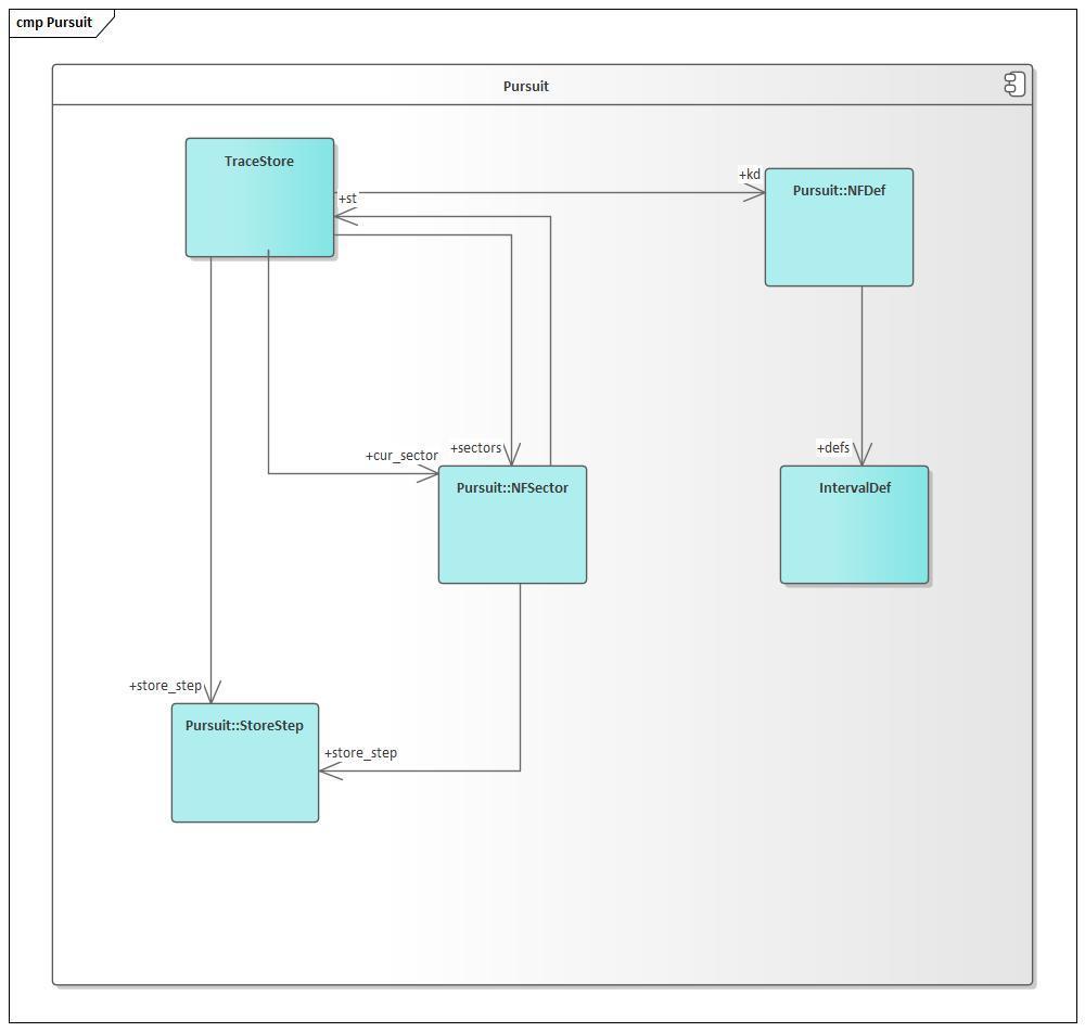
Here is one of the header files in C++ (we picked a small one to keep the book shorter :-)) — Fig. 5.6: C++ Header File:
class StoreStep
{
public:
    USHORT delta;

    void SetCM(USHORT cm) { delta = cm; }
    USHORT GetCM() { return delta; }
    USHORT GetSpeed() { return CalcSpeedCMS(delta, 1L); }
};
White Box of 1.3: Calibrate
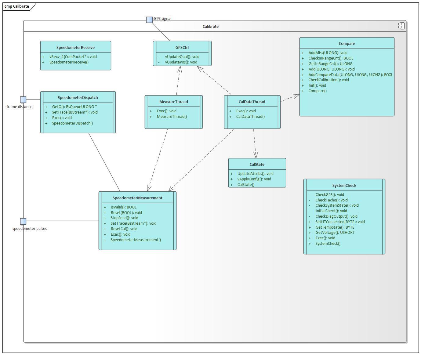
The building block Calibrate contains six threads (shown as “active classes” with a class symbol with parallel lines).
Data are collected concurrently from the speedometer and the GPS. It compares the two and checks their consistency all the time.