Traffic Pursuit Unit arc42 section 7
Deployment View
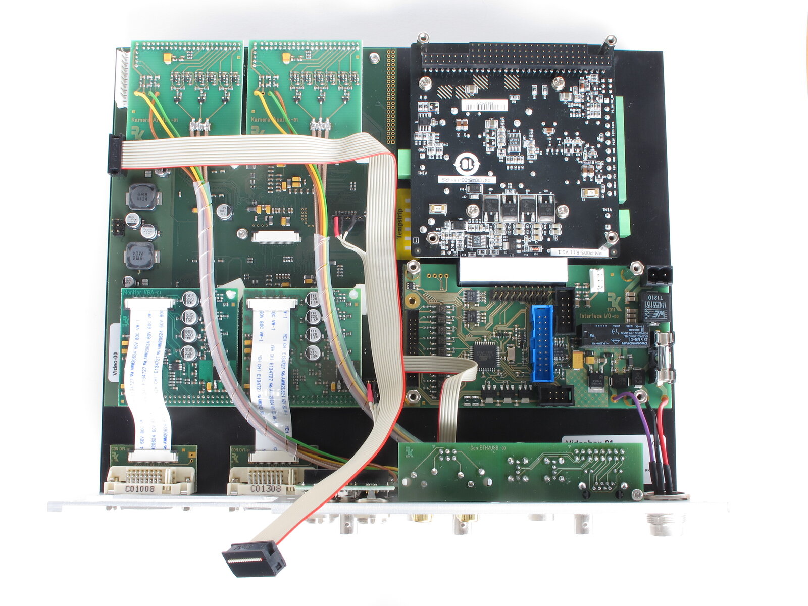
The following picture shows the inside of the TPU hardware, an industrial rack with the main PC board and several other Printed Circuit Boards (PCBs).
7.1 Deployment Level 1
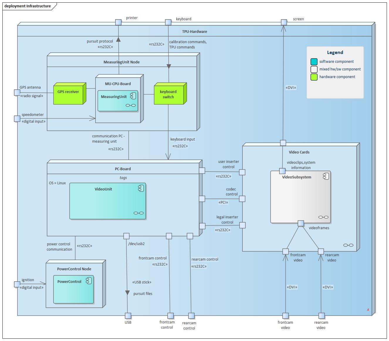
The following UML diagram shows this hardware structure.
1. MeasuringUnit Node
This node mainly consists of a base PCB on which the MU-CPU-Board, the GPS receiver module and the multiplexer are mounted.
MU-CPU-Board
- CPU: ARM processor, 200 MIPS at 180 MHz
- multiple RS232 lines with speeds up to 115 kBaud
Keyboard Switch
forwards the keyboard input either to the MU-CPU-Board or the PC board, depending on the operating mode of the MeasuringUnit. In stand-alone mode the user input is handled in the MeasuringUnit. In video mode it is handled by the PC board.
GPS receiver
transforms the GPS antenna signal into location information forwarded to the MU-CPU-Board.
- binary SiRF protocol or NMEA protocol
2. PC-Board
is the central processor of the TPU, mainly controlling all video functions of the system and storing relevant results.
- CPU: Intel CPU, xx cores
- running RT Debian Linux
- multiple RS232 lines with speeds up to 115 kBaud
3. Video Cards
This node contains all hardware for video processing. Its details are described in the next chapter.
7.2 Deployment Level 2
3.1 Video Cards (Details)
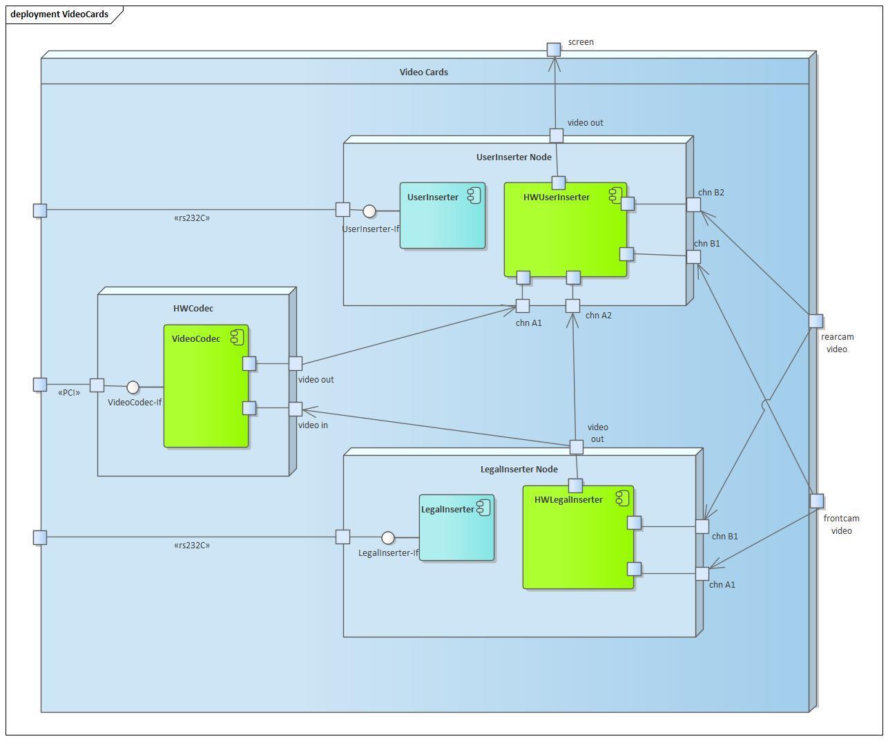
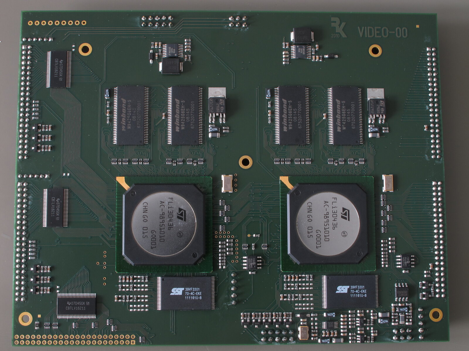
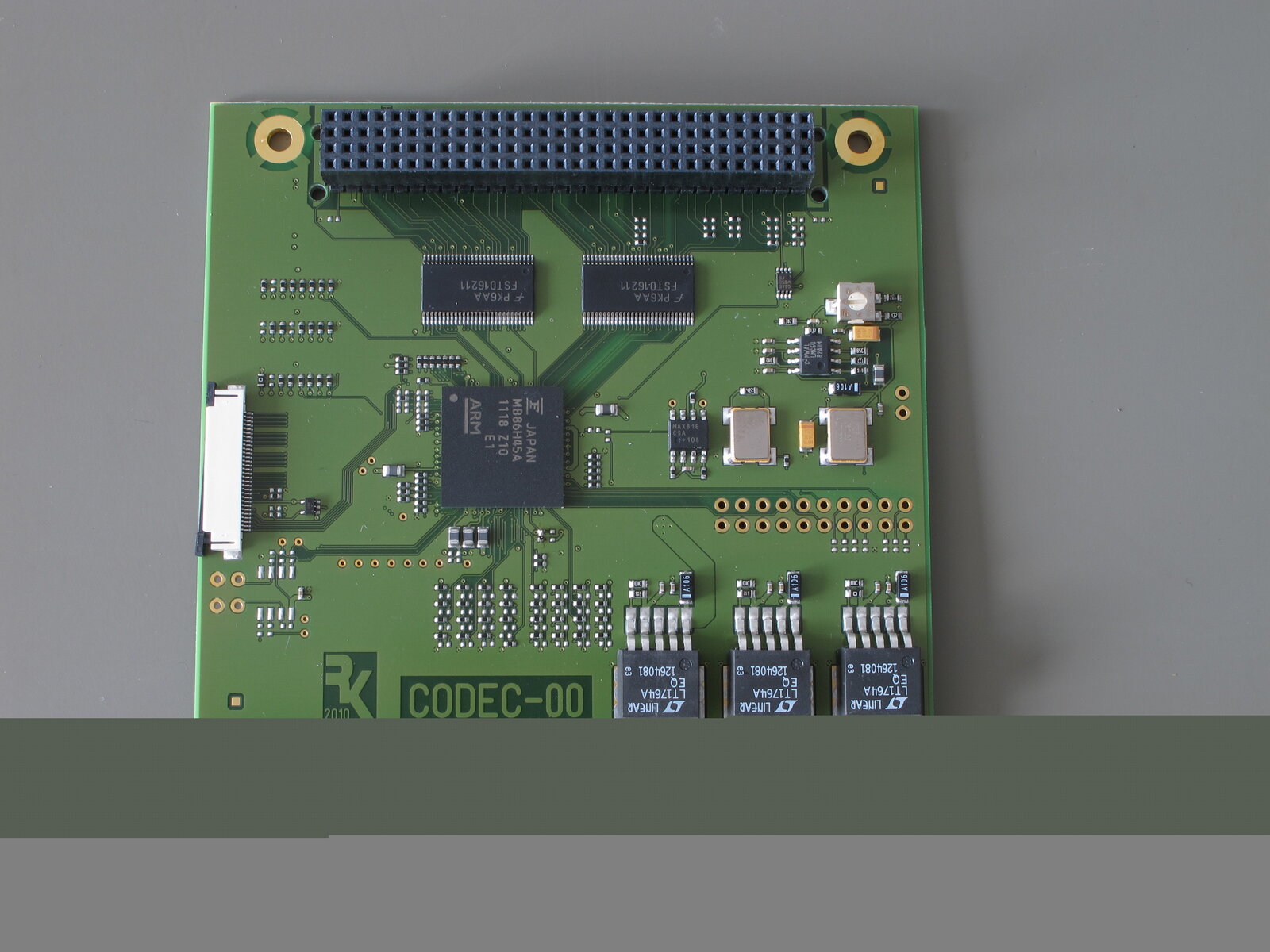
The video cards consist of two PCBs: one PCB contains two video inserters (UserInserter node and LegalInserter node, cf. Fig. 7.4) and the other one contains the codec (cf. Fig. 7.5).